Page 3 of 66

Posted: Wed Jun 25, 2008 3:50 pm
by retepsnikrep
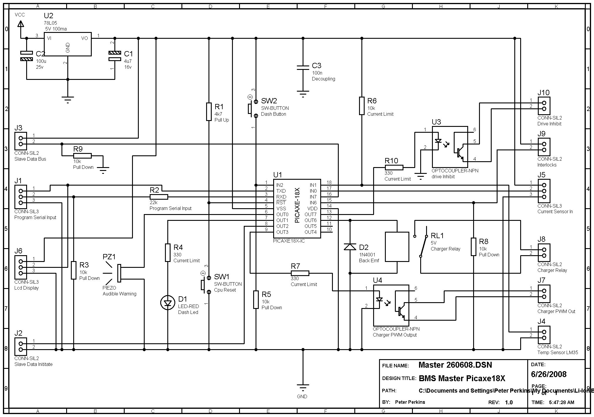
My initial Master board design will have an onboard lm335 temp sensor input, where the actual sensor can be put were you like, I will bury mine in middle of my pack to get an overall pack temp.

It will also have an input for the slave data bus obviously.

An output to initialise the slave data cascade which connects to slave 1.

An onboard piezo audible warning device.

A 2 pin output for a off board led warning indicator.

A 3 pin output for the serial LCD display.

A 3 pin input for onboard programming (Software upgrade)

A 3 pin isolated current sensor input probably based on a hall effect device.

A 2 pin opto isolated pwm output to control charger.

An onboard micro reset switch in case of hangs during use/testing

A 2 pin input for a conrol switch to be used with the software to select functions /menus etc on lcd.

It will operate from the 12v vehicle aux supply either switched with the ignition or independently. So charging can take place with vehicle ign off.

It will also have a 2 pin opto isolated drive inhibit output so can't be driven while charging from mains.

Also have a 2 pin 12v relay output to control fail safe charger cut off.

Might add more as we go. I'll try and transfer my basic schematic from paper to PC this week. :shock:

Posted: Thu Jun 26, 2008 9:23 am
by GregsGarage
The master board plan sounds pretty comprehensive. 8)
In my case I am splitting my pack into 2 packs, so it would be good to be able to read pack temp on both. I suspect that this may be the case for a number of people. Maybe room in the design for extra optional temp sensors, even if they are not implemented right away.

Also had an idea regarding the slave boards. The pic can be put to sleep and woken with an interrupt, so use the fact that you are sending an interrupt once a second to keep it awake. When the master decides that there is no activity to monitor (no driving or charging happening) it stops sending interrupts and the slave boards all go to sleep, lowering battery drain.

To implement add a counter variable in the main program loop to increment by 1 every cycle and check to see if it has reached a value of say 60 (ie. 1 minute), and put the chip to sleep if true. When the program jumps to the interrupt routine reset the counter to zero, there by keeping the pic awake.

The bad news is that I don't think it can be implemented using the picaxe basic, might have to be done in assembly :( The good news is that this isn't necessary for the chip to work and can be done after it has been proven to work otherwise. :D

Posted: Thu Jun 26, 2008 3:26 pm
by retepsnikrep
Yes I have considered the sleep/low power mode option I'll explore that later on.

Once Basic code is working nicely we can then use assembler programing direct and buy cheaper non picaxe chips!

Here is the initial Master schematic, lots to do with this but comments welcome.

www.solarvan.co.uk/master260608.jpg

Might use the keyboard input so you can plug in a ps2 keyboard to make changes to software parameters. :?

Testing, Testing

Posted: Mon Jun 30, 2008 3:16 pm
by retepsnikrep
Had one Slave and Master veroboard prototype working on bench today talking to each other over opto isolated serial bus at 2400baud. This gives a scan rate for 50 cell pack of just over a second, not bad, and not far off my initial design spec. :)

That could be halved if I went to 8bit resolution instead of 10bit for cell V. To keep 10 bit resolution two bytes have to be transmitted, with 8 bit only a single byte needs to be sent over the link. :?

I'll think about it, but would rather keep resolution in favour of scan speed at this stage. Working hard on slave pcb's now and hope to order a few (10) to make up for further testing.

Still making the odd tweak to the schematic :wink:

Updated slave code below.

I may well implement some oversampling, so whilst slave is not sending data it is working out average Voltage for the cell using as many adc conversions as it can fit in between the interupt driven data requests.

I'll test the sleep function once I have a few boards made up to play with, Slave average current consumption whilst running is currently <1ma. Rises to 5-10ma when transmitting data.

Lot's to do.

Master Software

Posted: Tue Jul 01, 2008 12:39 pm
by retepsnikrep
Did a fair bit on Master software last night. Not quite ready to run but not far off. Should have a workable version ready by the time I have my boards built and cells arrive.

www.solarvan.co.uk/Master030708.txt
www.solarvan.co.uk/Master030708.bmp

www.solarvan.co.uk/Slave030708.txt
www.solarvan.co.uk/Slave030708.bmp

Basic for donkeys

Posted: Tue Jul 08, 2008 9:52 am
by dillond666
Hi folks,

Peter, could you possibly explain in simple terms, the following bit of the slave code as mathmatical operations have never been my strong point.

`Add cell voltage inverting and conditioning
`routine here to make cell V value
`*25/25 to improve integer math accuracy +- 0.02 RESULT is * 1000

CellVoltage = RefVADC *25 /RefADC * 100 /25

I have bought the picaxe 8m and 18x project boards and the green book thingy. Thanks for bringing the picaxe to my attention, it is a fascinating bit of kit, my imagination is doing overtime!

Re: Basic for donkeys

Posted: Tue Jul 08, 2008 10:54 am
by retepsnikrep
dillond666 wrote:Hi folks,

Peter, could you possibly explain in simple terms, the following bit of the slave code as mathmatical operations have never been my strong point.

`Add cell voltage inverting and conditioning
`routine here to make cell V value
`*25/25 to improve integer math accuracy +- 0.02 RESULT is * 1000

CellVoltage = RefVADC *25 /RefADC * 100 /25

I have bought the picaxe 8m and 18x project boards and the green book thingy. Thanks for bringing the picaxe to my attention, it is a fascinating bit of kit, my imagination is doing overtime!


Ahh Got me :wink: , I had to get some help on this as well from the excellent Picaxe forum.

http://www.picaxeforum.co.uk/showthread.php?t=8624

The Picaxe Basic is limited to integer only arithmetic with a max 16 bit value of 65356 or something. So all arithmetic has to take this into account and result must fit into a 16bit word.

The Picaxe 08M adc10 input has 10 bits of resolution that's 1024bits or 0-1023.

My Picaxe 08M is measuring the 1.25v ref voltage. That's the only stable voltage!

The result of this reading of the static ref V will change as the pic supply (cell voltage) changes. So you have work out the result.

So Imagine the cell voltage is 4V that would give an adc10 result for the 1.25v ref of 319

1023/4*1.25=319

If the cell Voltage is 2V that would give an adc10 result for the 1.25v ref of 639

1023/2*1.25=639

The equation (CellVoltage = RefVADC *25 /RefADC * 100 /25) basically scales the result up to make maximum use of the full 16 bit integer maths available to reduce errors and convert result.

Picaxe basic maths is strictly left to right so discarding any decimal places along the way the equation with a 4v supply is below.

1279 * 25 = (31975) / 319 = (100) * 100 = (10000) / 25 = 400 (4.00v)

Try it for 2V (639) and see what you get. :shock:

I still don't fully understand all of it but it works so that's fine by me. 8)

Posted: Tue Jul 08, 2008 10:10 pm
by dillond666
Wow, that makes my little peabrain hurt! It's slowly sinking in though. Those guys on the picaxe forum are real boffins.

For my application I will be monitoring 12v agm's so hopefully I can just power the picaxe through a 5v regulator and feed the analogue input through a voltage divider arrangement.

Thanks for the help, I'm having fun learning from the code you have written so far.

Posted: Wed Jul 09, 2008 6:24 am
by retepsnikrep
dillond666 wrote:Wow, that makes my little peabrain hurt!


And Mine :shock:

If you are monitoring 12v agm's it's easy peasy lemon squeezy. Just power the pic with a stable 5v supply using 100ma 78L05 or equivalent. Then as you say feed voltage into one of the adc's with a PD calaculated to give you the full range you require but not taking the PIC above 5v or below 0v on the input whatever the soc. You don't need the stable REf and half that equation either so probably cheaper as well. Certainly fewer required. You can probably use my master/slave design/software as well later with a few tweaks to the code. Watch the current drain with a cheapo series regulator, might be better to use buck converter or dc-dc to get the right voltage to reduce current consumption. Try one and see.

Updated Schematics and PCB update.

Posted: Thu Jul 10, 2008 1:07 pm
by retepsnikrep
Slave layout is nearing completion on PCB. It will be approx 50mm x 100mm double sided (components only on the top) with slots/holes for upto 8mm cell posts covering 60-85mm distance between centre of cell terminals. That should fit 40-100ah TS/High Power cells. I can't go long enough to fit holes on the pcb for 200AH TS cells as the board won't fit on my 40ah cells. However an extension terminal or flying leads could just be soldered to the board to make it fit the bigger cells.

Latest docs

www.solarvan.co.uk/Master100708.txt
www.solarvan.co.uk/Master100708.jpg

www.solarvan.co.uk/Slave080708.txt
www.solarvan.co.uk/Slave100708.jpg

I've noticed it's a bit lonely in this thread :(