electricmini wrote:Ok, just having a quick look over it, and I had a few thoughts:
a few resistors, specifically where you have a bidirectional PIC
pin acting as an input - if the software goes nuts and sets this pin to
be an output whilst you're driving a signal in, you'll get a short through
the PIC. Most likely it'll cause a latchup, possibly damage the PIC's
port pin. A simple series resistor (100 ohm, or 1k ohm) takes care of this.
There's no protection against reverse polarity or a cell going open-circuit:
an on-board fuse and a reverse-biased zener/transient suppressor
across the supply would help
Is the LM385 reference diode the right way around?
Looks backwards to me... (designed to be used like a zener)
I presume you're planning on converting the reference diode's voltage,
then using that to give us the cell voltage? Also gives us a reference to use when measuring the temp from the LM335
(this is not intended as a slam, just a few things I thought of)
I tend to write PIC code using either CCS's C complier or the microchip
C compilers, been a while since I resorted to assembly!
There is a variant of the 8-pin PIC family, that has a built-in AtoD module,
and an analogue comparator module (the PIC12F683). This would allow
us to monitor the cell voltage, with the PIC in sleep mode, just waking
up if the cell volts drops or if it's talked to by the master?
Budget price from Microchip is sub $1 (if you buy enough!)
Bank on maybe £1 or £2 as you suggested for small quantities from Farnell / RS
I use Eagle for my pcb layout work (since they've gone and lost
our Orcad CDROM in work!! ), there's a free version which would probably
work ok with this small size board.
More later,
Richard
Thanks for those thoughts.
I've binned individual cell temp monitoring as I already have a pack solution in the Insight which does this.
The 1.25v LM385 is used as a V ref but as the voltage of the cell changes so does the result from the PIC adc

So I'll just use a lookup table in the master pic to get the correct cell V in a useable form to work out pack voltage.
If pic cell adc result is 200 then I know cell V is 2.00V (I've tested it)
If pic cell adc result is 500 then I know cell V is 3.80V (I've tested it)
The slave only needs to know that for instance at 3.8V the adc result will be X

above X it needs to turn on load.
So this version has a reduced component count and slave program is incredibly simple.
It also includes a (Non Isolated

) reprogramming connection, and an indicator led which flashes once when slave is polled by master (every second) to indicate normal operation.
`Battery Management System
`Slave Module Based on
`Picaxe 08M
`peter@solarvan.gotadsl.co.uk
`V1.1 230608
`Variables
`w0=Cell Voltage 0-1024 word 10bit
`Activate interrupt when pin3 goes high
setint %00001000,%00001000
`Main program loop
Main:
`Measure voltage reference
readadc10 2, w0
`Add cell voltage inverting and conditioning
`routine here to make cell V value
`between 0-1024 (3 significant digits)
`Calibrated so 2V = 200 with 1.25v LM385 V Ref
w0 = 834 - w0
`If cell V > 3.80v then turn on load
if w0 > 500 then
high 1
else
low 1
endif
`Pause 1 second
pause 1000
`Goto main loop
goto main
`Interrupt data transmission routine
Interrupt:
`Turn on indicator led
high 4
`Pause 0.1 of a second
pause 100
`Send raw cell voltage to Master
sertxd(w0)
`Activate interrupt when pin3 goes high
setint %00001000,%00001000
`Turn off indicator led
low 4
`Return from interrupt to main program
return
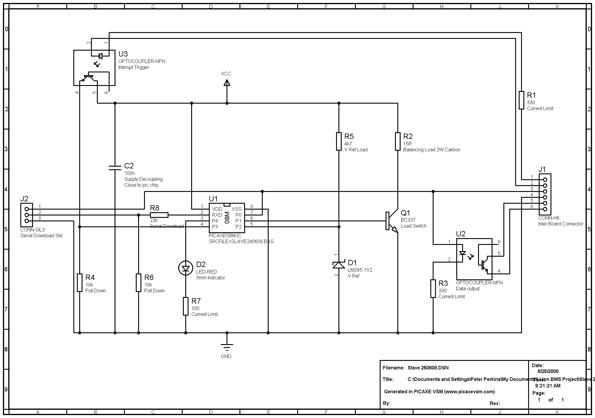
New schematic is here
www.solarvan.co.uk/slave250608.jpg
I'm almost ready to go to PCB layout now, anyone help me with this?
I'm happy with my once a second cell polling, from my experience with TS cells they are rugged and don't need to be micromanaged to the Nth degree
Yes lots of improvements could be made but again line has to be drawn and boards made up, I can tinker with software to my hearts content later. Looks like my batts could be on way from China by the end of June so need to get on!
So long as the master pic knows if data is missing/invalid/out of range and signals the fact along with shutting down charger etc then the Human computer has to investigate.
