Old BMS General Thread
Posted: Thu Jun 05, 2008 4:45 pm
Edit by Peter 10/08/09
Welcome to my opensource free BMS thread.
I have added some basic at a glance specs for the working BMS now. And a few basic pics of the setup. I strongly recommend you read all of this first post and wade through as much of the three threads as you can to understand how it all works, was developed and fits together
Specs for Modules are as follows.
*********** Slave Module Specification **********
Approx Parts Cost inc pcb $5.00 each.
One slave module per Lithium Cell.
Supply/Cell Voltage 1.75 - 5.00V DC.
Average Supply Current at 3.35v <1ma.
Voltage Ref LM 385 1.235V accuracy 1% Supply/Cell.
Voltage sensing maximum accuracy +/- 20mv.
Maximum balancing/bypass current with 15R resistor 333ma at 5.00V. Maximum Serial Master Bus data rate 9600 baud.
Maximum cell Capacity 65ah. Can be increased to 650ah.
Maximum 256 Slave Modules per Master Module.
Slave CPU Speed 8mhz with internal resonator.
Permitted Working Cell Voltage Range 1.75 - 4.30V.
************ Master Module Specification *************
Approx Parts Cost inc pcb $100.00 each.
One Master module per complete system.
Supply Voltage 8.00-30.00V DC or as limited by 5.00V 78L05 regulator.
CPU Supply Voltage 5.00V.
CPU Speed 8mhz with internal resonator.
Average Board Supply Current at 12.00v <100ma.
Maximum Serial Master Bus data rate 9600 baud.
Maximum Cell Capacity 65ah. Can be increased to 650ah.
Maximum Pack Voltage 650v.
Maximum Charge/Discharge rate depends on current sensor used.
Maximum 256 Slave Modules per Master Module.
Battery Pack Temp Sensor Range (-25 to +100C).
Composite Video Display data rate 9600 baud (SV2000 Video Chip).
Composite RCA Video Monitor Output 1V 75ohm PAL/NTSC.
Charger relay output is board supply voltage max 30v at 500ma.
Opto Isolated Charger/Controller Cutback outputs max 50ma 50v.
The Video display is limited to 16x9 characters in a 0-15 & 0-8 matrix.
Pictures & Videos
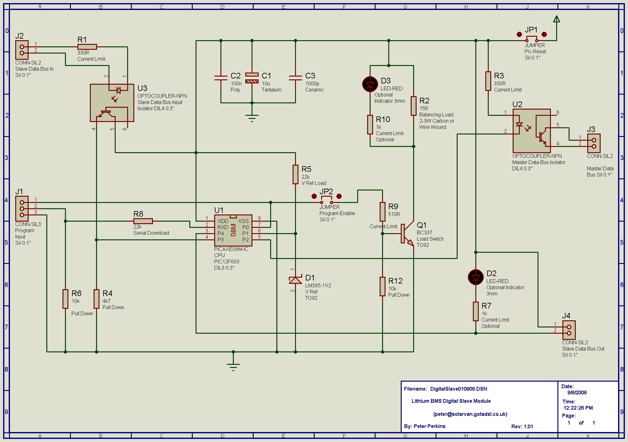
Digital Slave Schematic.
www.solarvan.co.uk/bms/DigitalSlave080908.jpg
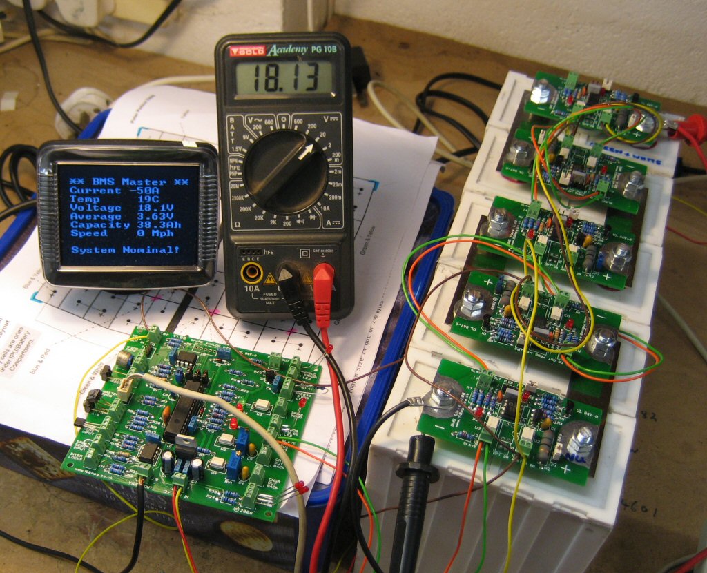
Early test run of Slaves & Master with display from 2008.
www.solarvan.co.uk/bms/MasterTest01.jpg
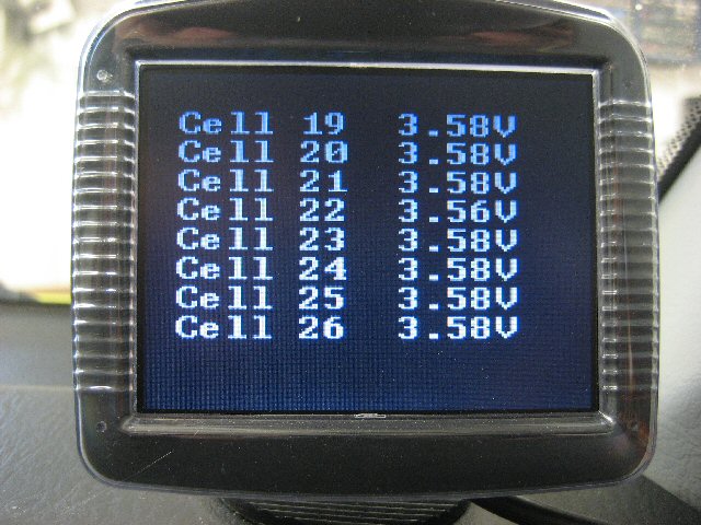
Latest software display showing various info.
www.solarvan.co.uk/bms/BMS050809001.jpg
www.solarvan.co.uk/bms/BMS050809004.jpg
Youtube BMS Tour Videos. Note there are several available from 2008.
http://www.youtube.com/watch?v=gAaSTQ2cWrk
http://www.youtube.com/watch?v=Wgyg41GIGxU
Hope that helps.
Peter
Edit by Peter 15/06/09
Dear All
This BMS thread has now grown a bit too large, so I'm am starting two additional threads to run alongside this one.
This BMS General thread contains all the work/discussion upto 15/06/09.
http://www.batteryvehiclesociety.org.uk ... php?t=1245
The BMS Hardware thread will contain any new work/discussion related to the hardware.
http://www.batteryvehiclesociety.org.uk ... php?t=2059
The BMS Software thread will contain any new work/discussion related to the software.
http://www.batteryvehiclesociety.org.uk ... php?t=2060
I hope this makes it a bit more manageable.
New readers should work through the General thread first until they reach 15/06/09, they should then look at specific hardware/software/general threads for further info.
Thanks Peter
Edit by Peter 12/01/09
Dear All
This Open Source BMS thread has grown dramatically over the last few months. Appologies for that, and to the BVS for using their bandwidth!.
At the moment I recommend those new here read the whole thread to be fully upto date with the software/ideas/principles & evolution of the idea. It's changed a lot and dipping in won't give you the full picture
There are now a number of other helpful and knowledgable contributors Thanks to them for their hard work and support.
The system is up and running in analogue mode in two UK vehicles now, Greg Fordyce's Fiat 126 EV, and my own PHEV Honda Insight. I hope to complete a further upgrade to my digital version with Master/Slave configuration and data display screen shortly. It's also being adapted and tested by several other contributors.
It is my intention to do a write up of the project later and perhaps provide a FAQ, parts list and various other bits and pieces. These things will take time so please bear with us. We welcome comments and ideas but I'm no expert so please be gentle
To help visitors the latest software/schematics etc will now be updated/available here as a zip archive below. Please note carefully version numbers for software and firmware requirements.
www.solarvan.co.uk/bms/BMSProject041208.zip
We/I make no claims about safety/effectiveness/reliability of this system.
It's just one of the many possible solutions now available for the management of EV batteries, and the standard disclaimer below applies.
This BMS carries no warranty or guarantee of any kind! It's used at your own risk, and I make no claims as to suitability for a particular function. Prospective users must evaluate the system before using it, and no liability will be entertained by anyone in any shape or form whatsoever.
The modules and software have been produced at low cost for the benefit of the EV & electronic community. The software is available free via the internet. Users may modify or adapt the system as they see fit. If you are not fully competent to work on potentially lethal battery systems and high voltages, then do not experiment with or use this system. Be aware that vehicle modifications can lead to invalidated insurance and warranty issues. You the end user remain fully liable for any modifications made to your vehicle.
A useful list of other available BMS designs for your consideration is here
http://liionbms.com/php/bms_options.php
Now back to the original message that started it all off
I thought I would start this thread to pull together BMS (Battery Management Systems) ideas for our projects, especially as a lot of us are currently investing in expensive Lithium Cells.
Now my ideas below won't be new I'm sure, and I hope everyone will contribute their own freely.
I've been dabbling and experimenting over last few weeks, and I do like the idea of an intelligent expandable BMS. Appologies in advance for my schematic skills, I could also only export the diagrams to a bmp file.
For any BMS there are an ever increasing number of desirable features,
but we have to draw the line somewhere for the sake of reproducability, practicality and cost.
I would like a BMS to monitor individual cells (in my new Li-fepo4 pack) or subpacks (In the case of the Insight)
I would like to know the cell V and temp, the pack capacity and voltage etc.
I've come up with a digital solution here which has many functions, only limited by the programmers collective ingenuity (Thats all of you ).
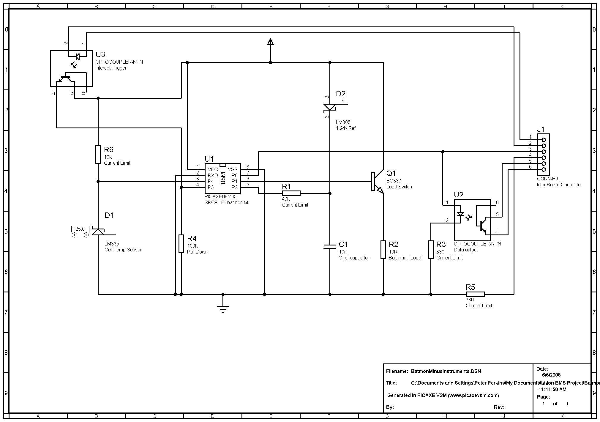
http://www.solarvan.co.uk/insight/digitalslave.bmp 356kb Schematic
Proteus design file here
http://www.solarvan.co.uk/insight/Batmo ... uments.DSN
This uses a Picaxe 08M or (12F683 pic) 8pin chip on each cell at a cost of about £2.00. (pcb and discrete components extra of course but if we could get it down to £5-8.00 a cell that's not bad.) Each cell is going to be fitted with one of these small circuits. The pic has a wide operating voltage from 2-5.5v so covers virtually all the various types of Li-Ion chemistry. It sits there 24/7 (need to keep the current drain to a minimum) running a cell monitoring program checking the cell (subpack) voltage against it's reference. It's also checking the cell temp, and activating it's balancing load if the cell goes over Max V. Now this idea uses an opto isolated serial bus for comms with the master PIC and dashboard display. All the serial opto outputs are connected in parallel so the cells have a common data bus.
The master pic pulls the interupt opto of cell one high and triggers an initial delay of say 0.1 seconds in the slave pic, the slave then starts the serial data output routine which dumps the cell data onto the bus for the master to receive and record. The act of data transmission triggers the interupt on cell two which waits for 0.1 seconds and then transmits it's data, add infinitum along the pack. The master recieves and checks all the data (Missing data can simply trigger an alarm condition etc) it then acts on data as reqd, calculating pack voltage from sum of cells, checking for over temp condition, etc etc etc.
Note on the first cell in the pack the master PIC would be connected to (pins 1 and 2) of the interboard connector to initiate the interupt sequence, the cell 1 slave would then connect it's output (pins 3 and 4) to the input (pins 1 and 2) of the next slave. Hope that makes sense, like a cascade effect. Bit of work to do on timing of data etc and all slaves must run the same software.
I'm off on hols now for a couple of weeks, I'll take a few schematics and have a further think. More ideas very welcome.
Here is a first draft slave PIC code
`Battery Management System Slave Module
`Based on Picaxe 08M microcontroller
`Original concept, hardware and code by Peter Perkins
`peter@solarvan.gotadsl.co.uk
`V1.00 280508
`Byte Variables for speed
`b1 = Cell voltage
`b2 = Cell temperature
`Balancing voltage is set at >3.75v For Li-fepo4 cells
start: `Initialise program and variables/interrupts as reqd
setint %00001000,%00001000 `Activate interrupt when pin 3 goes high
main:
low 2 `Pull pin 2 low to draw current through the ref 1.25v diode
pause 100 `Wait 0.1 of a second
input 2 'Turn off current and turn pin 2 back to an input
readadc 2, b1 `Measure the voltage stored across the capacitor
b1 = 255 - b1 `Invert the value of b1 so higher voltage = higher value
If b1 > 170 then `Turn on cell balancing load if voltage >3.75v
high 1 `Turn on load resistor
else
low 1 `Turn off load resistor
endif
readadc 4,b2 `Read the cell temperature into variable b2
goto main `Goto main loop
interrupt: `Send cell data to master Picaxe via opto serial bus
pause 100 `Wait 100 milliseconds to ensure data received OK and prior Pic has sent data
`This may be cut or removed depending on hardware response
sertxd(b1,b2) `Send raw cell/slave data to master, include :-Cell V, Cell temp
setint %00001000,%00001000 `Reset the interrupt and wait for another data request.
return `Return from interrupt to main program.
Once everything is working as reqd I could probably buy a job lot of the bare slave PIC's and program them in assembler with the final code.
The Picaxe basic is nice and easy for development though and can be simulated using Proteus VSM software. So any experts on schematics and pcb development want to lend a hand Come on down!
Picaxe stuff/info is here
http://www.rev-ed.co.uk/picaxe/
I'm going to make up three slave boards when I get back from hols and clag them onto three of my old TS cells, I'll fire them up and see how the idea works in practise. I don't really see any major limit to the number of cells/slaves you could have except time taken to poll them all may become excessive or the parallel leakage of the data opto may become an issue. I think a pack scan rate of once a second if I can acheive it would be good.
Peter[/b]
Welcome to my opensource free BMS thread.
I have added some basic at a glance specs for the working BMS now. And a few basic pics of the setup. I strongly recommend you read all of this first post and wade through as much of the three threads as you can to understand how it all works, was developed and fits together
Specs for Modules are as follows.
*********** Slave Module Specification **********
Approx Parts Cost inc pcb $5.00 each.
One slave module per Lithium Cell.
Supply/Cell Voltage 1.75 - 5.00V DC.
Average Supply Current at 3.35v <1ma.
Voltage Ref LM 385 1.235V accuracy 1% Supply/Cell.
Voltage sensing maximum accuracy +/- 20mv.
Maximum balancing/bypass current with 15R resistor 333ma at 5.00V. Maximum Serial Master Bus data rate 9600 baud.
Maximum cell Capacity 65ah. Can be increased to 650ah.
Maximum 256 Slave Modules per Master Module.
Slave CPU Speed 8mhz with internal resonator.
Permitted Working Cell Voltage Range 1.75 - 4.30V.
************ Master Module Specification *************
Approx Parts Cost inc pcb $100.00 each.
One Master module per complete system.
Supply Voltage 8.00-30.00V DC or as limited by 5.00V 78L05 regulator.
CPU Supply Voltage 5.00V.
CPU Speed 8mhz with internal resonator.
Average Board Supply Current at 12.00v <100ma.
Maximum Serial Master Bus data rate 9600 baud.
Maximum Cell Capacity 65ah. Can be increased to 650ah.
Maximum Pack Voltage 650v.
Maximum Charge/Discharge rate depends on current sensor used.
Maximum 256 Slave Modules per Master Module.
Battery Pack Temp Sensor Range (-25 to +100C).
Composite Video Display data rate 9600 baud (SV2000 Video Chip).
Composite RCA Video Monitor Output 1V 75ohm PAL/NTSC.
Charger relay output is board supply voltage max 30v at 500ma.
Opto Isolated Charger/Controller Cutback outputs max 50ma 50v.
The Video display is limited to 16x9 characters in a 0-15 & 0-8 matrix.
Pictures & Videos
Digital Slave Schematic.
www.solarvan.co.uk/bms/DigitalSlave080908.jpg
Early test run of Slaves & Master with display from 2008.
www.solarvan.co.uk/bms/MasterTest01.jpg
Latest software display showing various info.
www.solarvan.co.uk/bms/BMS050809001.jpg
www.solarvan.co.uk/bms/BMS050809004.jpg
Youtube BMS Tour Videos. Note there are several available from 2008.
http://www.youtube.com/watch?v=gAaSTQ2cWrk
http://www.youtube.com/watch?v=Wgyg41GIGxU
Hope that helps.
Peter
Edit by Peter 15/06/09
Dear All
This BMS thread has now grown a bit too large, so I'm am starting two additional threads to run alongside this one.
This BMS General thread contains all the work/discussion upto 15/06/09.
http://www.batteryvehiclesociety.org.uk ... php?t=1245
The BMS Hardware thread will contain any new work/discussion related to the hardware.
http://www.batteryvehiclesociety.org.uk ... php?t=2059
The BMS Software thread will contain any new work/discussion related to the software.
http://www.batteryvehiclesociety.org.uk ... php?t=2060
I hope this makes it a bit more manageable.
New readers should work through the General thread first until they reach 15/06/09, they should then look at specific hardware/software/general threads for further info.
Thanks Peter
Edit by Peter 12/01/09
Dear All
This Open Source BMS thread has grown dramatically over the last few months. Appologies for that, and to the BVS for using their bandwidth!.
At the moment I recommend those new here read the whole thread to be fully upto date with the software/ideas/principles & evolution of the idea. It's changed a lot and dipping in won't give you the full picture
There are now a number of other helpful and knowledgable contributors
The system is up and running in analogue mode in two UK vehicles now, Greg Fordyce's Fiat 126 EV, and my own PHEV Honda Insight. I hope to complete a further upgrade to my digital version with Master/Slave configuration and data display screen shortly. It's also being adapted and tested by several other contributors.
It is my intention to do a write up of the project later and perhaps provide a FAQ, parts list and various other bits and pieces. These things will take time so please bear with us. We welcome comments and ideas but I'm no expert so please be gentle
To help visitors the latest software/schematics etc will now be updated/available here as a zip archive below. Please note carefully version numbers for software and firmware requirements.
www.solarvan.co.uk/bms/BMSProject041208.zip
We/I make no claims about safety/effectiveness/reliability of this system.
It's just one of the many possible solutions now available for the management of EV batteries, and the standard disclaimer below applies.
This BMS carries no warranty or guarantee of any kind! It's used at your own risk, and I make no claims as to suitability for a particular function. Prospective users must evaluate the system before using it, and no liability will be entertained by anyone in any shape or form whatsoever.
The modules and software have been produced at low cost for the benefit of the EV & electronic community. The software is available free via the internet. Users may modify or adapt the system as they see fit. If you are not fully competent to work on potentially lethal battery systems and high voltages, then do not experiment with or use this system. Be aware that vehicle modifications can lead to invalidated insurance and warranty issues. You the end user remain fully liable for any modifications made to your vehicle.
A useful list of other available BMS designs for your consideration is here
http://liionbms.com/php/bms_options.php
Now back to the original message that started it all off
I thought I would start this thread to pull together BMS (Battery Management Systems) ideas for our projects, especially as a lot of us are currently investing in expensive Lithium Cells.
Now my ideas below won't be new I'm sure, and I hope everyone will contribute their own freely.
I've been dabbling and experimenting over last few weeks, and I do like the idea of an intelligent expandable BMS. Appologies in advance for my schematic skills, I could also only export the diagrams to a bmp file.
For any BMS there are an ever increasing number of desirable features,
but we have to draw the line somewhere for the sake of reproducability, practicality and cost.
I would like a BMS to monitor individual cells (in my new Li-fepo4 pack) or subpacks (In the case of the Insight)
I would like to know the cell V and temp, the pack capacity and voltage etc.
I've come up with a digital solution here which has many functions, only limited by the programmers collective ingenuity (Thats all of you
http://www.solarvan.co.uk/insight/digitalslave.bmp 356kb Schematic
Proteus design file here
http://www.solarvan.co.uk/insight/Batmo ... uments.DSN
This uses a Picaxe 08M or (12F683 pic) 8pin chip on each cell at a cost of about £2.00. (pcb and discrete components extra of course but if we could get it down to £5-8.00 a cell that's not bad.) Each cell is going to be fitted with one of these small circuits. The pic has a wide operating voltage from 2-5.5v so covers virtually all the various types of Li-Ion chemistry. It sits there 24/7 (need to keep the current drain to a minimum) running a cell monitoring program checking the cell (subpack) voltage against it's reference. It's also checking the cell temp, and activating it's balancing load if the cell goes over Max V. Now this idea uses an opto isolated serial bus for comms with the master PIC and dashboard display. All the serial opto outputs are connected in parallel so the cells have a common data bus.
The master pic pulls the interupt opto of cell one high and triggers an initial delay of say 0.1 seconds in the slave pic, the slave then starts the serial data output routine which dumps the cell data onto the bus for the master to receive and record. The act of data transmission triggers the interupt on cell two which waits for 0.1 seconds and then transmits it's data, add infinitum along the pack. The master recieves and checks all the data (Missing data can simply trigger an alarm condition etc) it then acts on data as reqd, calculating pack voltage from sum of cells, checking for over temp condition, etc etc etc.
Note on the first cell in the pack the master PIC would be connected to (pins 1 and 2) of the interboard connector to initiate the interupt sequence, the cell 1 slave would then connect it's output (pins 3 and 4) to the input (pins 1 and 2) of the next slave. Hope that makes sense, like a cascade effect. Bit of work to do on timing of data etc and all slaves must run the same software.
I'm off on hols now for a couple of weeks, I'll take a few schematics and have a further think. More ideas very welcome.
Here is a first draft slave PIC code
`Battery Management System Slave Module
`Based on Picaxe 08M microcontroller
`Original concept, hardware and code by Peter Perkins
`peter@solarvan.gotadsl.co.uk
`V1.00 280508
`Byte Variables for speed
`b1 = Cell voltage
`b2 = Cell temperature
`Balancing voltage is set at >3.75v For Li-fepo4 cells
start: `Initialise program and variables/interrupts as reqd
setint %00001000,%00001000 `Activate interrupt when pin 3 goes high
main:
low 2 `Pull pin 2 low to draw current through the ref 1.25v diode
pause 100 `Wait 0.1 of a second
input 2 'Turn off current and turn pin 2 back to an input
readadc 2, b1 `Measure the voltage stored across the capacitor
b1 = 255 - b1 `Invert the value of b1 so higher voltage = higher value
If b1 > 170 then `Turn on cell balancing load if voltage >3.75v
high 1 `Turn on load resistor
else
low 1 `Turn off load resistor
endif
readadc 4,b2 `Read the cell temperature into variable b2
goto main `Goto main loop
interrupt: `Send cell data to master Picaxe via opto serial bus
pause 100 `Wait 100 milliseconds to ensure data received OK and prior Pic has sent data
`This may be cut or removed depending on hardware response
sertxd(b1,b2) `Send raw cell/slave data to master, include :-Cell V, Cell temp
setint %00001000,%00001000 `Reset the interrupt and wait for another data request.
return `Return from interrupt to main program.
Once everything is working as reqd I could probably buy a job lot of the bare slave PIC's and program them in assembler with the final code.
The Picaxe basic is nice and easy for development though and can be simulated using Proteus VSM software. So any experts on schematics and pcb development want to lend a hand
Picaxe stuff/info is here
http://www.rev-ed.co.uk/picaxe/
I'm going to make up three slave boards when I get back from hols and clag them onto three of my old TS cells, I'll fire them up and see how the idea works in practise. I don't really see any major limit to the number of cells/slaves you could have except time taken to poll them all may become excessive or the parallel leakage of the data opto may become an issue. I think a pack scan rate of once a second if I can acheive it would be good.
Peter[/b]